Purchase IoTKit
Please refer to TQLOne for options to purchase your copy of IoTKit
Meet Your IoTKit
List of things that are contained in the IoTKit
Name | Image | Description |
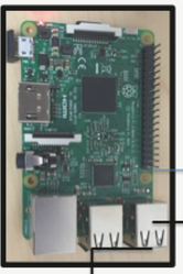
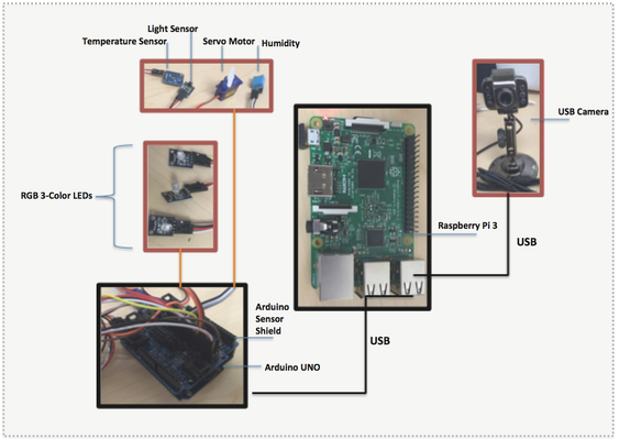
Raspberry Pi 3 Model 3 | | The Raspberry Pi 3 is the third generation Raspberry Pi. It replaced the Raspberry Pi 2 Model B in February 2016. Compared to the Raspberry Pi 2 it has: - A 1.2GHz 64-bit quad-core ARMv8 CPU
- 802.11n Wireless LAN
- Bluetooth 4.1
- Bluetooth Low Energy (BLE)
Default login password for Raspberry pi are: pi / raspberry |
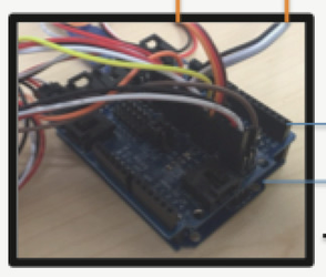
Arduino Uno and Arduino Sensor Shield | | The Uno is a microcontroller board based on the ATmega328P. It has 14 digital input/output pins (of which 6 can be used as PWM outputs), 6 analog inputs, a 16 MHz quartz crystal, a USB connection, a power jack, an ICSP header and a reset button. |
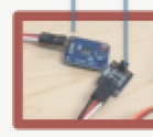
Sensors | | - Ambience Light Sensor
- Thermistor
- DHT11 sensor
|
USB camera | | The USB camera is easy to use and it is interfaced to Pi. |
Micro Servo motor | | The micro servo motor can rotate at angle between 0 and 180 degrees and it is to be interfaces to the Arduino. |
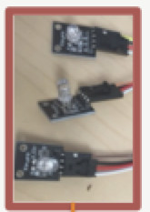
| RGB 3-Color LED Module | | This LED light can be set in one of the three colors – Red, Green or Blue. Provided 3 lights. |
The following steps will setup the Wireless connection on raspberry pi.
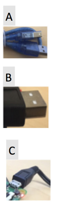
- Connect USB cable (A in Figure above) from Arduino to Raspberry Pi USB Port (Any of the four available)
- Connect USB cable (B in Figure above) from USB Camera to Raspberry Pi USB Port (Any of the four available)
- Connect mini USB power cable (C in Figure above) to Raspberry Pi mini USB power port and power supply.
- Wait for Raspberry Pi to startup.
- Raspberry Pi will start in in Wireless router mode giving out Wi-Fi network name as IOTKit-Pi3
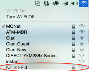
- Connect your laptop to IOTKit-Pi3 Wi-Fi network name using password atomiton
- Launch a web browser and type http://1.1.1.1:8080/fid-kitsetupui/index.html
- Configure your personal Wi-Fi Network. Note that you can configure multiple Wi-Fi Networks.
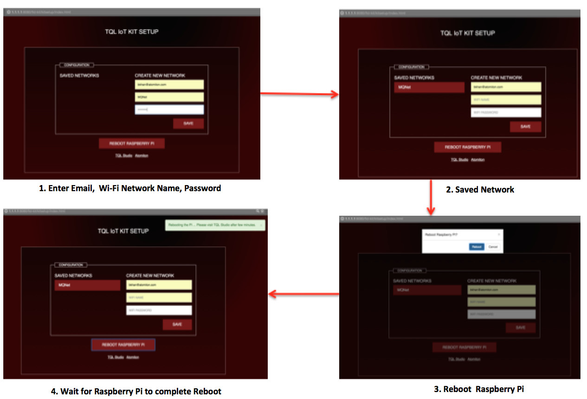
- After Raspberry Pi rebooted, connect your laptop back to your personal Wi-Fi network.
- Login to TQLStudio portal using your TQLStudio credentials.
- Click on any of your project and go to Thing Spaces to view the IP address assigned to IoTKit Raspberry Pi
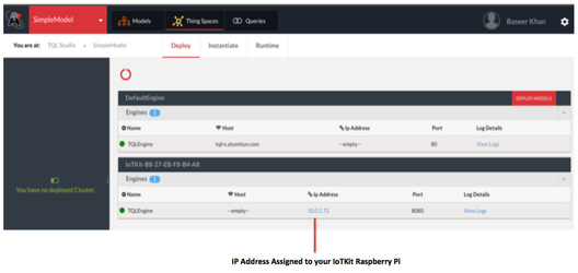
- Launch TQLEngine User Interface by clicking on the IP Address link
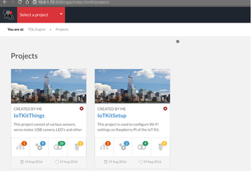
- Login to TQLEngine UI default credentials [Username: TQLEngine@atomiton Passwrod: tql123]

- You will find two default projects loaded - IoTKitThings and IoTKitSetup
- Refer to Working with IoTKit Things below.
Working with IoTKit Things
Working with Sensors
Detect Serial Port
<Query>
  <Find format="version,Known">
    <SerialPortModel>
      <ID ne=""/>
    </SerialPortModel>
  </Find>
  <if condition="$Response.Message.Value/Find/Status eq 'Success'">
    <then>
      <DeleteAll>
        <SerialPortModel>
          <ID ne=""/>
        </SerialPortModel>
      </DeleteAll>
    </then>
  </if>
  <Create>
    <SerialPortModel>
      <PortName>
        $Null()
      </PortName>
      <Baudrate>
        9600
      </Baudrate>
      <DefaultPort>
        /dev/cu.usbmodem1411
      </DefaultPort>
    </SerialPortModel>
  </Create>
</Query>
Get Serial Port
<Query>
  <Find format="version, known">
    <SerialPortModel>
      <ID ne=""/>
    </SerialPortModel>
  </Find>
</Query>
Get Serial Port Response
PortName attributes "Known" value contains the Serial Port on which the Arduino is connected to the Raspberry Pi. The value here is: /dev/ttyACM0
<Find Status="Success" Format="version, known">
  <Result>
    <SerialPortModel>
      <ID>K264G7FLAAAH6AABAF46QU4Z</ID>
      <PortName Value="" Known="/dev/ttyACM0
" Version="1"/>
      <Baudrate Value="9600" Known="9600" Version="1"/>
      <DefaultPort Value="/dev/cu.usbmodem1411" Known="/dev/cu.usbmodem1411" Version="1"/>
    </SerialPortModel>
  </Result>
</Find>
Arduino Sketch
The Arduino Sketch uses two other libraries,
- OneWire
- Dallas Temperature
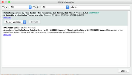
this libraries can be imported in the Arduino IDE, below are the steps to install the libraries
- In the toolbar menu select sketch, then Include Library→ Manage Libraries option.
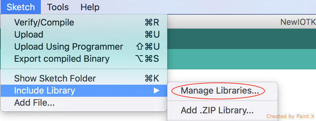
- Search for the Dallas Temperature library and Install it, similarly search for one wire library and install it.
#include <math.h>
#include <Servo.h>
#include <OneWire.h>
#include <DallasTemperature.h>


#define ONE_WIRE_BUS 12 /*-(Connect to Pin 12 )-*/

/*-----( Declare objects )-----*/
/* Set up a oneWire instance to communicate with any OneWire device*/
OneWire ourWire(ONE_WIRE_BUS);

/* Tell Dallas Temperature Library to use oneWire Library */
DallasTemperature sensors(&ourWire);

//Create servo object
Servo myservo;
int sensorPinL = A4; // select the input pin for the potentiometer

String inData;
int redPinOne = 1;
int greenPinOne = 2;
int bluePinOne = 3;

int redPinTwo = 5;
int greenPinTwo = 6;
int bluePinTwo = 7;

int redPinThree = 9;
int greenPinThree = 10;
int bluePinThree = 11;

String getTemperature() {
  sensors.requestTemperatures();
  String tempStr = "TEMPC:" + String(sensors.getTempCByIndex(0)) + "#TEMPF:" + String(sensors.getTempFByIndex(0));
  //String tempStr = "TEMPC:" + String((int)sensors.getTempCByIndex(0)) + "#TEMPF:" + String((int)sensors.getTempFByIndex(0));
  return tempStr;
}

//KY015 DHT11 Temperature and humidity sensor
int DHpin = 8;
byte dat [5];
byte read_data () {
  byte data = 0;
  for (int i = 0; i < 8; i ++) {
    if (digitalRead (DHpin) == LOW) {
      while (digitalRead (DHpin) == LOW); // wait for 50us
      delayMicroseconds (30); // determine the duration of the high level to determine the data is '0 'or '1'
      if (digitalRead (DHpin) == HIGH)
        data |= (1 << (7 - i)); // high front and low in the post
      while (digitalRead (DHpin) == HIGH); // data '1 ', wait for the next one receiver
    }
  }
  return data;
}

void start_test () {
  digitalWrite (DHpin, LOW); // bus down, send start signal
  delay (30); // delay greater than 18ms, so DHT11 start signal can be detected

  digitalWrite (DHpin, HIGH);
  delayMicroseconds (40); // Wait for DHT11 response

  pinMode (DHpin, INPUT);
  while (digitalRead (DHpin) == HIGH);
  delayMicroseconds (80); // DHT11 response, pulled the bus 80us
  if (digitalRead (DHpin) == LOW);
  delayMicroseconds (80); // DHT11 80us after the bus pulled to start sending data

  for (int i = 0; i < 4; i ++) // receive temperature and humidity data, the parity bit is not considered
    dat[i] = read_data ();

  pinMode (DHpin, OUTPUT);
  digitalWrite (DHpin, HIGH); // send data once after releasing the bus, wait for the host to open the next Start signal
}


String getHumidity () {
  start_test ();
  String hum = "";
  hum = "HUMPCT:" + String(dat [0], DEC) + "." + String(dat [1], DEC);
  return hum;
}

int ledPin = 13; // select the pin for the LED

String getLight() {
  String amb = "";
  int sensorValue = 0; // variable to store the value coming from the sensor
  sensorValue = analogRead(sensorPinL);
  digitalWrite(ledPin, HIGH);
  delay(sensorValue);
  digitalWrite(ledPin, LOW);
  delay(sensorValue);
  amb = "AMB:" + String(sensorValue, DEC);
  return amb;
}


void setup()
{
  Serial.begin(9600);
  Serial.setTimeout(500);

  pinMode(redPinOne, OUTPUT);
  pinMode(greenPinOne, OUTPUT);
  pinMode(bluePinOne, OUTPUT);

  pinMode(redPinTwo, OUTPUT);
  pinMode(greenPinTwo, OUTPUT);
  pinMode(bluePinTwo, OUTPUT);

  pinMode(redPinThree, OUTPUT);
  pinMode(greenPinThree, OUTPUT);
  pinMode(bluePinThree, OUTPUT);
  pinMode (DHpin, OUTPUT);
  pinMode (ledPin, OUTPUT);
  myservo.attach(4);
  sensors.begin(); // For Temperature Sensor Begin Dallas Library

}


void RGB_control(String temp, int light)
{
  int redval = temp.charAt(0) - '0';
  int greenval = temp.charAt(1) - '0';
  int blueval = temp.charAt(2) - '0' ;

  switch (light)
  {
    case 1:
      digitalWrite(redPinOne, redval);
      digitalWrite(greenPinOne, greenval);
      digitalWrite(bluePinOne, blueval);
      break;
    case 2:
      digitalWrite(redPinTwo, redval);
      digitalWrite(greenPinTwo, greenval);
      digitalWrite(bluePinTwo, blueval);
      break;
    case 3:
      digitalWrite(redPinThree, redval);
      digitalWrite(greenPinThree, greenval);
      digitalWrite(bluePinThree, blueval);
      break;

  }
}

void loop() {
  inData = "";
  if (Serial.available() > 0)
  {
    int h = Serial.available();
    for (int i = 0; i < h; i++) {
      inData += (char)Serial.read();
    }

    if (inData.indexOf("RGB") >= 0)
    {
      RGB_control(inData.substring(6, 9),(int)(inData.charAt(4)-'0'));
    }
    else
    {
      myservo.write(inData.toInt());
    }
  }

  Serial.println(getTemperature() + "#" + getHumidity() + "#" + getLight());
  delay(1000);
}